- Your cart is empty
- Continue Shopping


Essential Ultrasound Controls And How To Use Them: Part 1
- blog
- Posted on
-
 by
Michelle Macauley
by
Michelle Macauley - 0 comments

Great knobology is the heart of an ultrasound exam. But we are only as good as what we know. This 4-part series will explore 20 essential ultrasound controls that can make or break an ultrasound image.
This is Part 1 of a 4 part Essential Ultrasound Controls Every Sonographer Should Know Series. See the overview here.
Confession time! I was a Sonographer for over a year before I knew how to fully utilize each of the 20 ultrasound controls that we will cover in this 4 part series. Ultrasound school is 2 years of information overload. Pump the information in and then dump it out quickly, to get ready to receive the next large batch of data. Fortunately, enough of the major tenets stick around inside your brain to complete a basic scan. The genuine moments of learning, however, come the hard way – when you find yourself in front of a 500 lb patient, on a ventilator, who cannot hold their breath for you, at 3 in the morning. In that hour, you switch from book knowledge of ultrasound knobology to genuine real-life application. This is the juncture when you move from good to great.Ultrasound Image Formation
Before we begin our ultrasound knobology journey, we must first discuss dots. An ultrasound image consists of a multitude of dots with different brightness levels. But where do these dots come from and why are they different colors?What Are Ultrasound Echoes?
An ultrasound sound wave goes into the tissue, encounters a structure, and a portion of that sound wave returns to the transducer as a reflection (known as an echo). The pattern and brightness of these echoes give information about the characteristics of the tissue it came from. Each echo returning to the transducer creates one dot of information. The color of the dot (gray, black or white) depends on the strength of the returning echo. We often refer to ultrasound as B-Mode, known as brightness mode, which indicates that multiple dots of different brightness form the ultrasound image.Ultrasound Scan Lines
A sound wave generates multiple returning echoes as the pulse travels further into the tissue, sending back echoes from multiple depths. Each sound wave creates one line of dots, composed of the returning echoes at each depth. A line of dots forms a line of the ultrasound image, known as a scan line. We create an ultrasound image from multiple scan lines stitched together. The more scan lines an image consists of, the higher the image resolution (detail).Echogenicity
The amount of reflection (how much sound wave returns to the transducer vs traveling deeper into the tissue) depends on the type of tissue the pulse encountered. The brightness of the dot is determined by the strength of the reflection, an ultrasound concept known as echogenicity. To determine the echogenicity of an area in the breast, we compare the color of the area with the medium gray echogenicity of the fat in the breast. The tissue will appear bright when the reflected echoes strongly reflect the sound wave. This is known as hyperechoic, and it indicates the area has more echoes compared to the surrounding breast fat. When the tissue weakly reflects the sound wave, it’s known as hypoechoic, which appears as a dark gray color on the ultrasound image, showing that the area has fewer echoes than the breast fat. The tissue will appear black when there is no reflection from the tissue, known as anechoic. The entire sound wave travels deeper into the tissue, and there’s an absence of reflected echoes. When the number of reflected echoes is like the reflection of fat in the body, the reflected echoes will appear medium gray. We know this as isoechoic. When there are multiple echogenicities, and an area has both cystic and solid components, it is known as complex.
Essential Ultrasound Control 1: Output Power
An ultrasound machine has 3 brightness controls: Gain, TGC and output power. Gain and TGC are controls that are frequently adjusted several times during an exam. The output power control must be used with caution, and as the last control to be manipulated. Let’s explore why.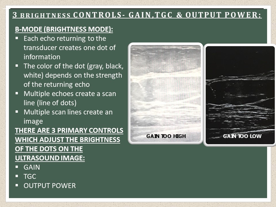
Output Power Defined
The Output Power control increases or decreases the brightness of the ultrasound image by changing the strength of the pulse of sound sent into the patient’s body. A stronger pulse means all returning echoes (reflected sound waves) are stronger, and that it increases proportionately all the echoes of the image in brightness. A weaker pulse (such as when the Output Power level is decreased) results in weaker echoes, which translates to all echoes within the Ultrasound image being decreased equivalently in brightness.Output Power And Patient Safety
When considering how to improve an ultrasound image, and adjusting controls, consider first the impact on the patient. This is an ultrasound safety principle known as ALARA (As Low As Reasonably Achievable). Good ultrasound knobology always weighs the potential risk to the patient vs the need to obtain a diagnostic study. Though ultrasound is considered an inherently safe technology, no test is without risk. To improve image quality, first adjust TGC, depth, gain, frequency and focal zones. Only adjust the output power control higher as a last resort, because it affects the strength of the pulse sent into the body.Optimal Output Power For An Ultrasound
The output power control should be adjusted so that the lowest level that provides a diagnostic image is used. This ensures a high quality image is produced, while we keep patient safety at the forefront of the exam.
Other Names For The Output Power Control
Various names for the output power ultrasound control among different manufacturers include: acoustic output, output power, AO.Essential Ultrasound Control 2: Gain
Gain is one of the 3 brightness controls on an ultrasound machine. Gain is one of the most frequently adjusted Ultrasound controls during an exam, and is essential to great Ultrasound knobology. It should always be adjusted after the TGC control.Gain Defined
The ultrasound gain control increases or decreases the brightness of the entire image by boosting the strength of the electrical signals that have already returned to the ultrasound machine. It boosts all the signals, but only in proportion to their original strength (for instance, a black dot on the image would not suddenly become bright white, rather, it would become a slightly brighter shade of black, i.e. gray). The gain Ultrasound control does not change the strength of the pulse that’s sent into the patient’s body, but amplifies the signals that have already returned to the machine.Optimal Gain Level For An Ultrasound
The gain control should be set so that the image is not over or undersaturated with brightness. A good rule of thumb is to adjust the gain control so that fat in the image is a medium shade of gray. The art of learning what is too bright vs too dark of an image comes in time, as ultrasound knobology skills develop over time.
Other Names For The Gain Control
Various names for the gain ultrasound control among different manufacturers include: B-mode (brightness mode), B, 2D.Essential Ultrasound Control 2: TGC
The next control on our ultrasound knobology journey is known as TGC, or time gain compensation. TGC control is one of the 3 brightness controls on an ultrasound machine. It should always be the first ultrasound brightness control adjusted during an exam before reaching for the gain or output power controls.TGC Defined
The TGC control boosts signals within the ultrasound machine at different depths in the image. Like gain, TGC does not change the strength of the pulse sent into the body, it amplifies signals that have already returned to the machine. The TGC control is used to achieve uniform brightness at all levels of the image by correcting for attenuation (loss of strength of a sound wave as it either encounters a dense structure or penetrates further into the tissue). Sliding the TGC levers (either independently or together) increases or decreases the brightness at that depth in the image. Most ultrasound machines have a row of knobs, allowing precise adjustments at multiple depths. Some portable machines only have two knobs, allowing brightness to be adjusted only within the near and far fields.Optimal TGC Level For An Ultrasound
The TGC control should be adjusted so that there’s equal brightness at all depths in the image, which generally translates into the far field TGC being moved brighter to account for the effects of the attenuation of the sound wave as it travels deeper into the tissue. TGC is one of the most under-utilized controls on an ultrasound machine and is a central tenant for great ultrasound knobology. Rather than reaching for the gain control, we should optimize the TGC control first. Adjust the TGC so that blood vessels and anechoic structures, like the normal gallbladder, are echo-free, but also so that tissue looks like tissue (muscle should be clearly visualized as muscle, fat as fat, etc.). A rookie mistake is to decrease the gain or the TGC to make anechoic structures anechoic, but to leave adjacent tissues equally dark, so that it’s hard to even delineate which type of tissue it is. When taking an ultrasound image, the entire image matters, not just the area of interest.How To Decide Whether To Adjust Gain vs TGC
Stuck on whether you should adjust the Gain control or the TGC control? Take a close look at your image. Is the entire image too bright or too dark? Time to adjust the gain, which will affect the brightness of the image as a whole. Are parts of your image darker/brighter than other portions? Do anechoic structures contain low level artifactual echoes? Can you clearly delineate each type of tissue throughout all depths on the image? If you said no to one or more of these questions, then the TGC control can help you correct each of these scenarios.
Other Names For The TGC Ultrasound Control
Various names for the TGC ultrasound control among different manufacturers include: TGC, slide pods, gain levers.Essential Ultrasound Control 4: Depth
Should we really care about the depth? It seems like such a mundane, unimportant ultrasound control. But did you know that having your image set at the proper depth can make the difference between a mediocre image and a great one? Let’s talk depth…Depth Defined
The depth control on an ultrasound machine adjusts how deeply the sound waves are penetrating into the body. There is a scale (measured in CM) on the side of the monitor that depicts the current depth. When depth is increased, the sound waves penetrate further into the body, and we can visualize deeper structures. An increased depth decreases the size of the FOV (field of view). When depth is decreased, the FOV widens, the sound waves do not penetrate as deeply into the tissues, and we can visualize more superficial structures.Optimal Depth Level For An Ultrasound
The depth should be adjusted so that the area of interest is in the mid to far field of the image, and we can clearly delineate the posterior edge of the structure (no portion is cut off). The area of interest needs to be the “star” of your image, with the least amount of extraneous information around it as possible. Two mistakes I commonly see when depth is being adjusted: the first mistake is too much depth. In this scenario, the area of interest is crammed way into the near field of the image, the FOV is narrowed, and there’s poor visualization of the structure because it’s too far away on the ultrasound image. The second mistake is not enough depth, where the bottom edge of a structure or mass is not visualized because the posterior edge is cut off and outside of the field of view of the image. Using depth is an art – you want enough depth to see the bottom edge, but not so much depth that your area of interest is too far away. It’s such a simple Ultrasound control that we often overlook as a key component of essential Ultrasound knobology.
Other Names For The Depth Ultrasound Control
Various names for the depth ultrasound control among different manufacturers include: depth, CM.Need to optimize a breast ultrasound image? Check out this quick how-to guide: HOW TO OPTIMIZE A BREAST ULTRASOUND IMAGE: 7 PITFALLS
Essential Ultrasound Control 5: Focus/Focal Zone
An understanding of the width of the Ultrasound beam is essential when discussing the focal zone control. An Ultrasound beam starts out as the same width as the transducer, then gradually tapers until it reaches its narrowest point (which is half the width as it began) and then it widely diverges.Focus Defined
A focus is the area of the Ultrasound beam that is the narrowest, and it’s represented on the Ultrasound monitor by an arrow on the side of the image. The focus is the area of the Ultrasound image that has the highest resolution.Focal Zone Defined
A focal zone is the area of the ultrasound beam that surrounds and encompasses the focus, where the beam is narrower. In an ultrasound image, the focal zone is the tissue at the level of the focus, and the tissue that is immediately above and below the focus. There is high image resolution in this area of the ultrasound, because the beam is narrower in this region.Near Field Defined
The top portion of the ultrasound image, which is the area of tissue that is most superficial on the image. In this area, the ultrasound beam starts out as the same width as the transducer, then gradually narrows. Resolution is lower in this region because the ultrasound beam is wider and it is located above the focal zone.Far Field Defined
The bottom portion of the Ultrasound image, which is the area of tissue deepest on the image. In this area, the Ultrasound beam widely diverges. Resolution is lower in this region because the Ultrasound beam is wider and it’s below the focal zone.Optimal Focal Zone Use For An Ultrasound
The focal zone control on an ultrasound machine narrows the ultrasound beam in a region to provide high resolution within that area of the image. The focal zone control can be raised or lowered on the ultrasound image, providing high resolution either higher or lower on the screen. There is also the ability to use multiple focal zones for high image resolution throughout more of the ultrasound image. Multiple focal zones provide high resolution through multiple areas of the image, but decrease frame rate. Therefore, the use of focal zones is always a trade-off between the need for high resolution vs the need for a high frame rate. The focal zone control is one of the top ten most important ultrasound controls and is crucial to great ultrasound knobology.When To Use A Solitary Focal Zone (Focus)
We use a solitary focal zone for most types of ultrasound imaging because it allows a high frame rate and provides adequate image resolution. When using a solitary focal zone, we should place the focal zone at the level of, or slightly below, the area of interest.When To Use Multiple Focal Zones (Foci)
Using multiple focal zones can dramatically decrease the frame rate. They primarily used multiple focal zones in breast ultrasound and other types of ultrasound, in which high resolution is more crucial to the exam than the need for a high frame rate. When using multiple focal zones, the lowest focal zone should be placed either at the bottom edge of the tissue being interrogated (such as at the level of the pectoralis muscle when evaluating the breast tissue), or at or slightly below the structure or mass that’s being evaluated (such as a thyroid lobe).
Other Names For The Focal Zone Ultrasound Control
Various names for the focal zone ultrasound control among different manufacturers include: focus, focal zone, or a line or bar on the side of the image.Conclusion
Put the ultrasound machine controls to work for you, don’t miss the opportunity to make your images shine from lack of knowledge about how different controls work. Struggling to make your area of interest the star of your image? There’s a control for that! Stuck on getting proper brightness and contrast levels within your image? Check and check. Multiple controls help you finesse contrast and brightness levels. Is your area of interest tough to delineate clearly? Yep! We’ve got a setting for that too! With a little know-how, great ultrasound knobology can make even terrible images diagnostic.Ready for round two? Check out the next post in this series “Essential Ultrasound Controls Every Sonographer Should Know and How to Use Them: Part 2.”
Check out the other articles in this series: Essential Ultrasound Controls Every Sonographer Should Know And How To Use Them: Part 3; Part 4.