- Your cart is empty
- Continue Shopping


AORTA ULTRASOUND: STOP DOING THESE 5 THINGS
- blog
- Posted on
-
 by
Michelle Macauley
by
Michelle Macauley - 0 comments
And start doing these 5 things instead to make your ultrasound images shine…

Table of contents
- #1- STOP MIXING UP THE AORTA AND THE IVC
- #2- STOP TAKING OFF-AXIS IMAGES OF THE AORTA
- # 3- STOP THESE 3 AORTA ULTRASOUND MEASUREMENT FAILS
- #4- STOP MIXING UP THE DIFFERENT SEGMENTS OF THE AORTA
- # 5- STOP USING COLOR DOPPLER INCORRECTLY
- HARNESSING THE POWER OF COLOR DOPPLER
- Doppler Angle & the Curvilinear Transducer
- COLOR DOPPLER SECRET 2- OPTIMIZE YOUR DOPPLER BOX SIZE & POSITION
- Optimizing Doppler Box Size
- Optimizing Doppler Box Position
- COLOR DOPPLER SECRET 3- SETTING THE CORRECT COLOR DOPPLER GAIN LEVEL
- Why the Doppler Gain Level is Key
- How to Set the Perfect Doppler Gain Level
- COLOR DOPPLER SECRET 4- IT’S ALL ABOUT THE SCALE
- Nyquist Limit
- Aliasing
- PRF/Scale Ultrasound Control
- BONUS COLOR DOPPLER SECRET- BEWARE OF PSEUDO-THROMBUS IN YOUR IMAGE
- What is Ultrasound Pseudo-Thrombus?
- How to Eliminate Pseudo-Thrombus
It’s your first general ultrasound protocol- the aorta ultrasound- and you’re so excited to dive right in! You place the transducer down and realize that capturing that perfect ultrasound image is much harder than you were anticipating. Here’s 5 common pitfalls that occur when we are first learning the aorta ultrasound protocol and how to conquer them.
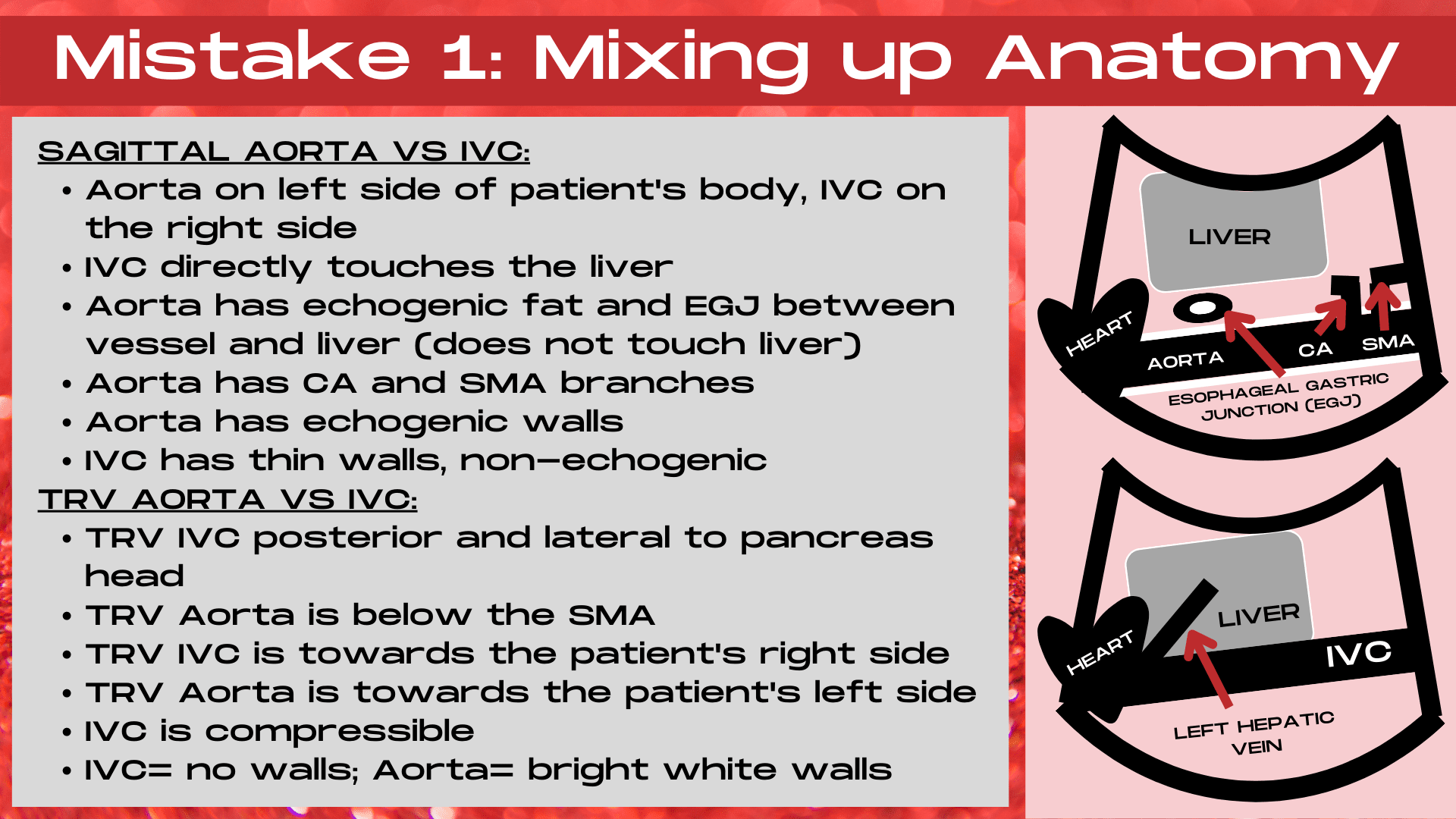
#1- STOP MIXING UP THE AORTA AND THE IVC
The most common mistake when first learning to image the sagittal aorta is mixing up the aorta and the IVC (inferior vena cava). Afterall, they are both anechoic, long, tubular structures. And to make it even more confusing, the IVC is often much easier to visualize on the image. So why keep looking when a beautiful anechoic tube keeps jumping out right in front of you? Because it’s crucial to ensure that you are in the right tube, not only because details are crucial, but also because these tubes get very different types of pathology.
DISTINGUISHING BETWEEN THE IVC & THE AORTA ON ULTRASOUND
Keys to Identifying the Aorta
When imaging the sagittal aorta, the aorta is going to be located on the left side of the patient’s body with echogenic fat and the esophagogastic junction (EGJ) located between the left lobe of the liver and the liver. A crucial distinction between the sagittal aorta and the sagittal IVC is that the aorta does not directly touch the left lobe of the liver, it’s located deeper on the ultrasound image than the IVC.
The aorta will be located on the left side of the patient’s body, is pulsatile and will have thick, hyperechoic walls.
Also, the aorta has thick, echogenic walls on the aorta and will be pulsatile. The aorta can be visualized pulsating on the image when in transverse. In the sagittal plane, the celiac axis and superior mesenteric branches can usually be readily visualized branching off of the aorta, often below the lateral edge of the left lobe on the liver.
The Aorta will be located below the SMA in the mid segment of the aorta when in transverse, located to the left side of the patient’s body and non-compressible when transducer pressure is applied due to it’s thick, hyperechoic walls.
Keys to Identifying the IVC
When imaging the sagittal IVC, the IVC will directly communicate with (touch) the liver. The IVC has thin walls often referred to as a “no-walls” appearance because they are not thick and hyperechoic like the walls of the aorta. The IVC is located towards the right side of the patient’s body. The left hepatic vein will be visible branching into the liver in the proximal segment of the sagittal aorta. It is easy to compress the sagittal aorta due to it’s thin walls, and the IVC may also collapse in response to patient respiration.
The IVC is located on the right side of the patient’s body, has “no-walls” and is compressible on an ultrasound image.
The IVC will have very thin walls and will be collapsable upon transducer pressure being applied in the transverse plane. It will be located to the right of the aorta, posterior and lateral to the pancreas head in the mid segment of the transverse IVC.
WANT TO LEARN ANOTHER ULTRASOUND SPECIALTY? HERE’S YOUR DEFINITIVE GUIDE! A START-TO-FINISH GUIDE TO PERFORMING A BREAST ULTRASOUND.
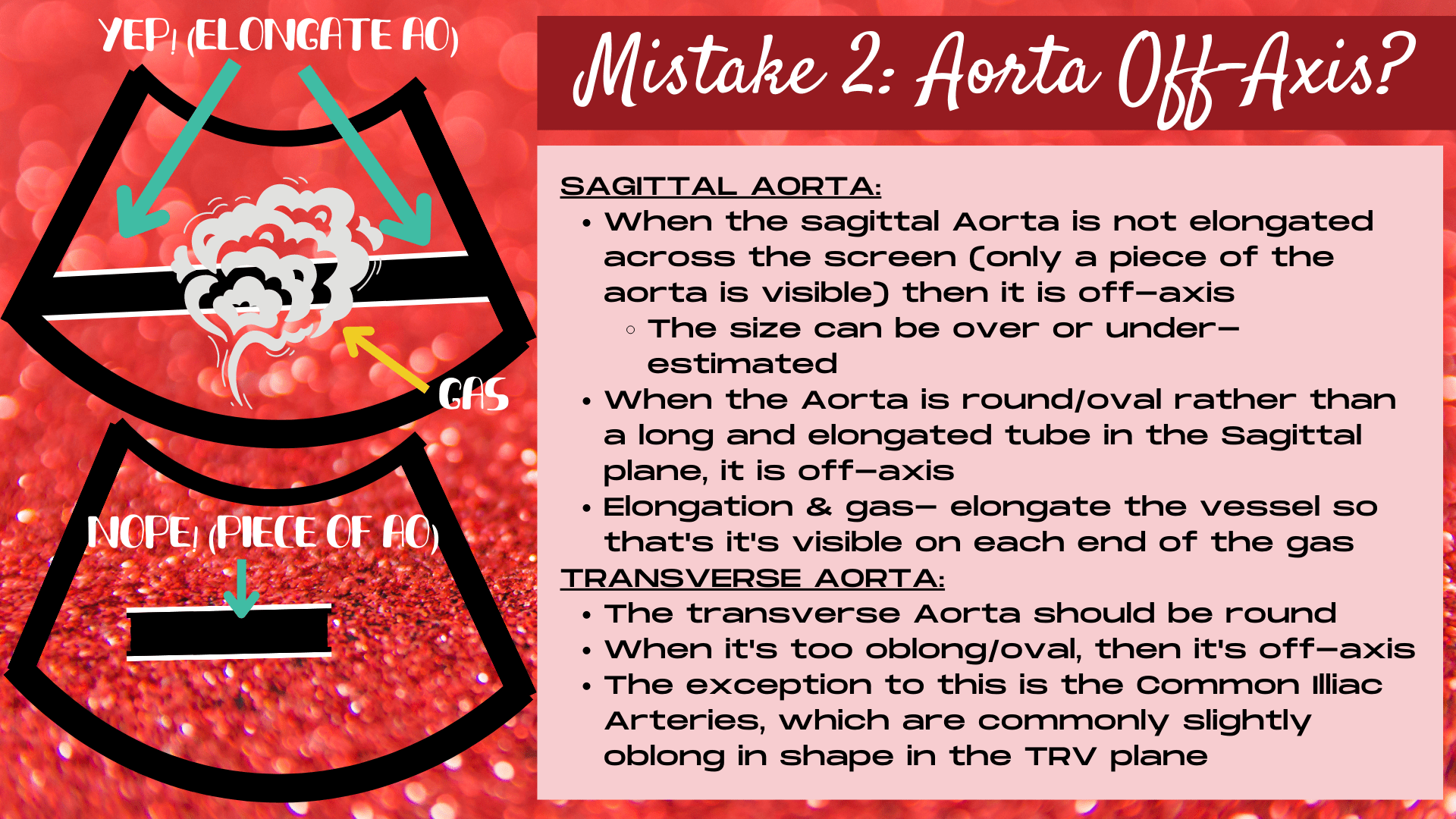
#2- STOP TAKING OFF-AXIS IMAGES OF THE AORTA
You’ve done it, you’ve captured your first images of the aorta on the ultrasound images, which was no easy feat. But it’s not enough to get a piece of the aorta on the image. An aorta ultrasound exam requires on-axis images in order for the exam to be diagnostic. But how do you know if your images are on or off-axis? Read on to learn the keys to capturing on-axis images, in both the sagittal and the transverse plane.
HOW TO ENSURE YOUR AORTA IMAGES ARE ON-AXIS
Capturing On-Axis Images of the Aorta in Sagittal
The aorta is on-axis in the sagittal plane when the aorta is elongated across the image. If only a piece of the aorta is captured in the sagittal plane, then the aorta is off-axis, and the aorta size could be under or over-estimated. If only a small piece of the long Aortic tube is visible, then it’s hard to know whether you are angling at a plane that’s capturing its true diameter. Also, if the aorta is off-axis, important pathology, such as an aneurysm or a dissection could be missed entirely or the extent of the disease could be miscalculated.
How to Achieve On-Axis Images When Gas Overlies Aorta
So what should you do when gas obscures a portion of the aorta? How do you elongate the vessel across the image if you cannot view all of the vessel? This is a common issue, especially in the mid aorta. And the answer is that you can still ensure that the aorta is elongated entirely across the image, despite the gas overlying part of the image, by showing the aorta on both ends of the image, around the gas shadowing. As long as the aorta is visible on both ends of the gas, the aorta is elongated and on-axis.
As long as the sagittal aorta is visible on both ends of any obscuring gas, the aorta is elongated and on-axis.
Creating On-Axis Images of the Aorta in Transverse
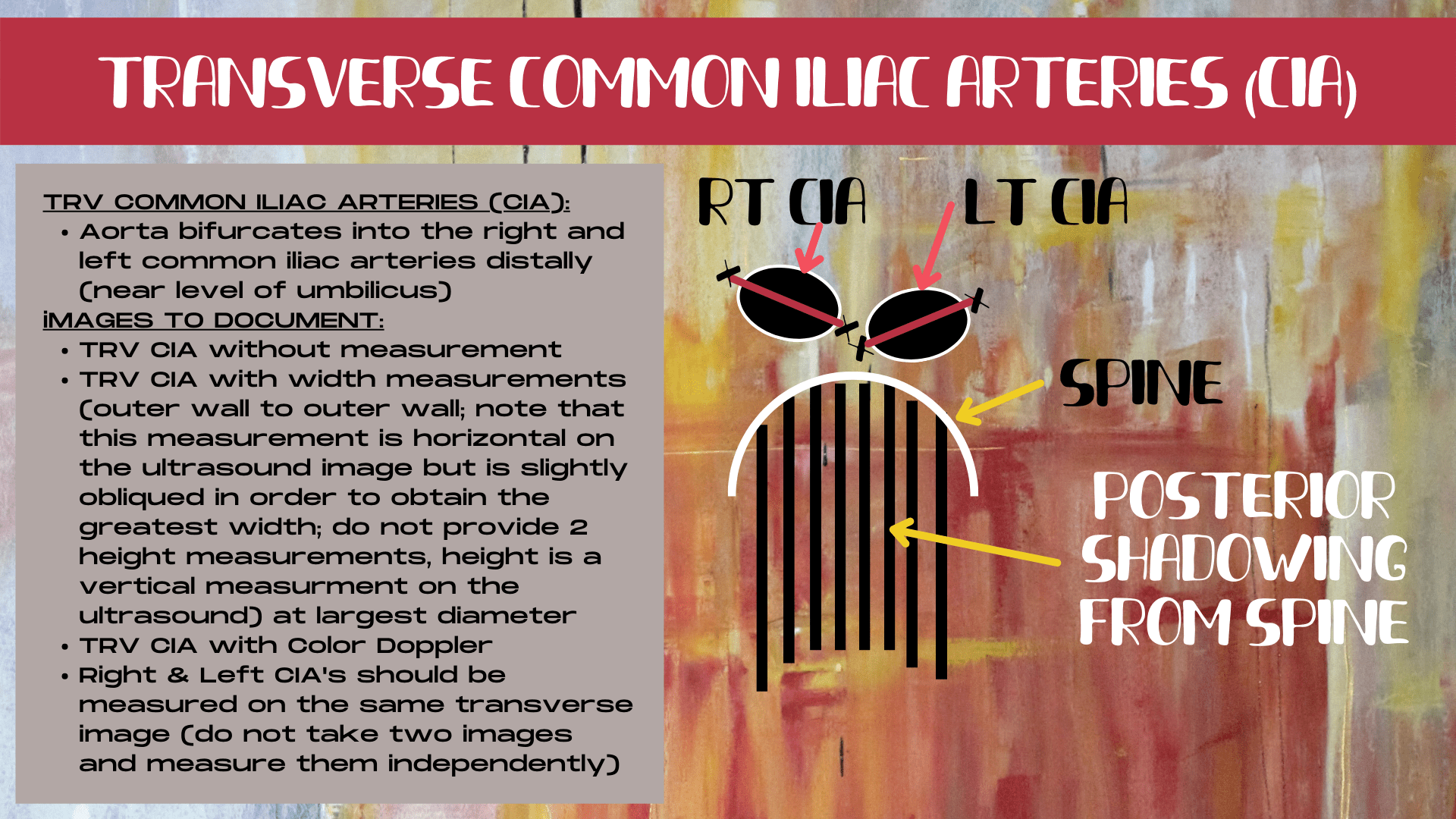
In the transverse plane, the aorta is on-axis when it is round. The closer the aorta gets to an oval or oblong shape, the more off-axis the transverse aorta is. Is it always possible to get a perfectly round aorta? No! But this is the shape that we strive to obtain. Now the exception to this is the transverse common illiac arteries. The transverse CIA’s are most commonly oblong, or oval in shape. The key to ensuring that the transverse CIA’s are on-axis is ensuring that your ultrasound probe is held in an exact transverse transducer plane.
LEARNING ULTRASOUND KNOBOLOGY? CHECK OUT THIS NEW SERIES- ESSENTIAL ULTRASOUND CONTROLS AND HOW TO USE THEM: PART 1, PART 2, PART 3, PART 4.
# 3- STOP THESE 3 AORTA ULTRASOUND MEASUREMENT FAILS
It’s so exciting to place your first set of measurement calipers on an ultrasound image. And it feels so satisfying, because how hard could this measuring thing really be? Turns out that measuring is one of the first ways to for an ultrasound image to veer off course. Let’s uncover the formula for measuring the aorta correctly, no matter the circumstances.
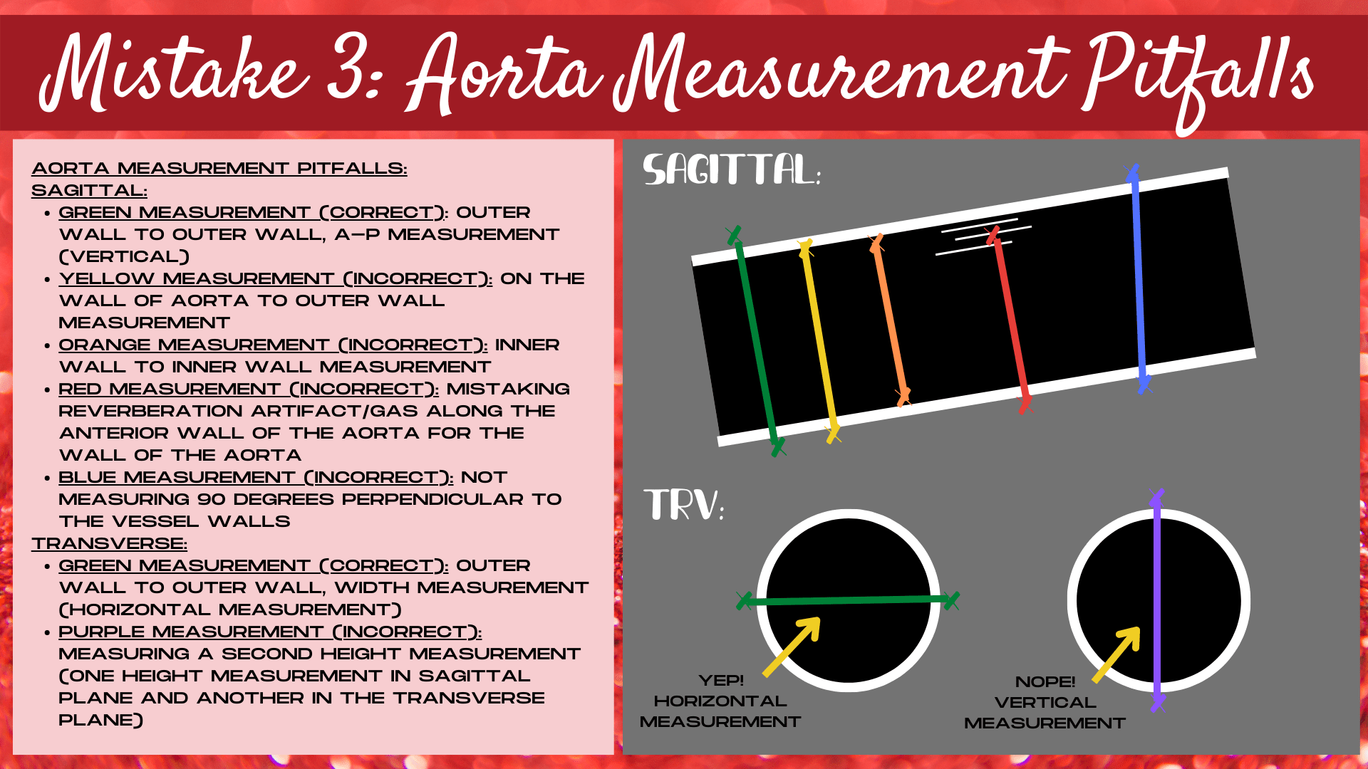
ONE: NOT MEASURING OUTER WALL TO OUTER WALL
It’s crucial to place the measurement calipers outside the echogenic aorta walls. The proper measurement is outer-wall to outer-wall. Now this doesn’t mean on-the-wall to outer-wall, outer-wall to inner-wall, way above or below the aorta wall, or inside the aorta lumen to outer-wall. The calipers should touch the hyperechoic outer walls of the aorta.
The calipers should be placed outer-wall to outer-wall and should touch the hyperechoic outer surface of the aorta walls when measuring the aorta.
Another pitfall is mistaking reverberation artifact within the aorta for the aorta wall and placing the caliper on top of the reverberation artifact instead of the wall. Or, having the gain turned down so low that the wall is not really visible and guessing the location of the aorta wall. If you can’t see the wall, don’t measure, as this will not be a true representation of aorta size.
TWO: MEASURING THE HEIGHT DIMENSION TWICE
Should your aorta measurement be horizontal or vertical on the ultrasound image? That is the million dollar question on every newbie ultrasound student’s mind. Horizontal or vertical, does it really make a difference? In which direction should each measurement be placed and why? The truth is, that if the calipers face the wrong direction on your ultrasound image, then not only are you not measuring the correct dimension (length, height or width), but you could be measuring one or more dimension twice.
If two vertical measurements are performed when measuring the aorta on ultrasound, then the height dimension has been measured twice.
This is especially common with the height dimension on an aorta ultrasound. A double measurement of the height is one of the most common measurement fails. If a vertical measurement is taken in the sagittal plane and another vertical measurement is taken in the transverse plane, then you have two height dimensions and no measurements for either of the other two dimensions (length and width).
THREE: NOT MEASURING 90 DEGREES PERPENDICULAR TO THE VESSEL WALLS
It’s tempting to want to always have every measurement either exactly horizontal or exactly vertical on the ultrasound image. We love symmetry, right? However, this is not how things tend to lie in the body. The body loves angles, and many organs do not follow exact horizontal and vertical planes.
Since the proximal aorta is deeper on the image than the mid and distal aorta, the sagittal aorta will often lie obliquely across the ultrasound image (unless the heel-toe transducer technique is applied to make the aorta lie exactly horizontal across the image). The heel-toe method is applied by pressing harder on the heel of the transducer (the portion that touches the palm of the hand) in order to minimize the angle of the aorta across the image. When this technique is applied, the aorta will lie exactly horizontal on the image, and an exactly vertical measurement can be applied to the sagittal aorta.
Calipers should be placed 90 degrees perpendicular to the walls of the vessel when measuring the aorta on ultrasound.
If the heel-toe technique is not practiced, then the aorta will stretch obliquely across the image with the proximal aorta deeper on the ultrasound image than the mid and more distal portions of the aorta. In this scenario, an exact vertical caliper measurement of the aorta diameter would over-estimate the size of the aorta. It’s crucial that the measurement is taken exactly 90 degrees perpendicular to the lie of the aorta walls in the sagittal plane in order to correctly determine the size of the vessel.
HERE’S HOW YOU SHOULD MEASURE THE AORTA
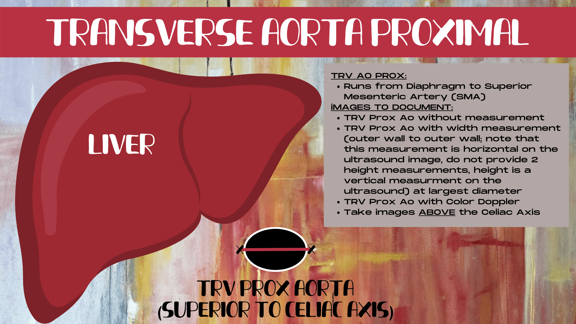
What are the secrets to the perfect aortic measurement? Most organs in the body should be measured in 3 dimensions: length, width and height. However, since the aorta is a long tube, a length measurement (which is always a horizontal measurement on an ultrasound image) wouldn’t provide much value.
Because of this, a length measurement is only performed of the aorta when an aneurysm is present. This is a dilation of a segment of the aorta. When an aneurysm is visualized, the length of just the aneurysm is measured, otherwise, the length measurement is not performed during an aorta ultrasound exam.
When measuring structures on an ultrasound, 3 measurements should be performed: length (horizontal measurement), height (vertical measurement) and width (horizontal measurement).
That leaves two other dimensions of measurement: height and width. Height, also known as the A-P, or anterior-posterior dimension is always a vertical measurement on an ultrasound and width is always a horizontal measurement. Thus, the standard three dimensions (length, height and width) should always be represented as horizontal, vertical and horizontal measurements on an ultrasound.
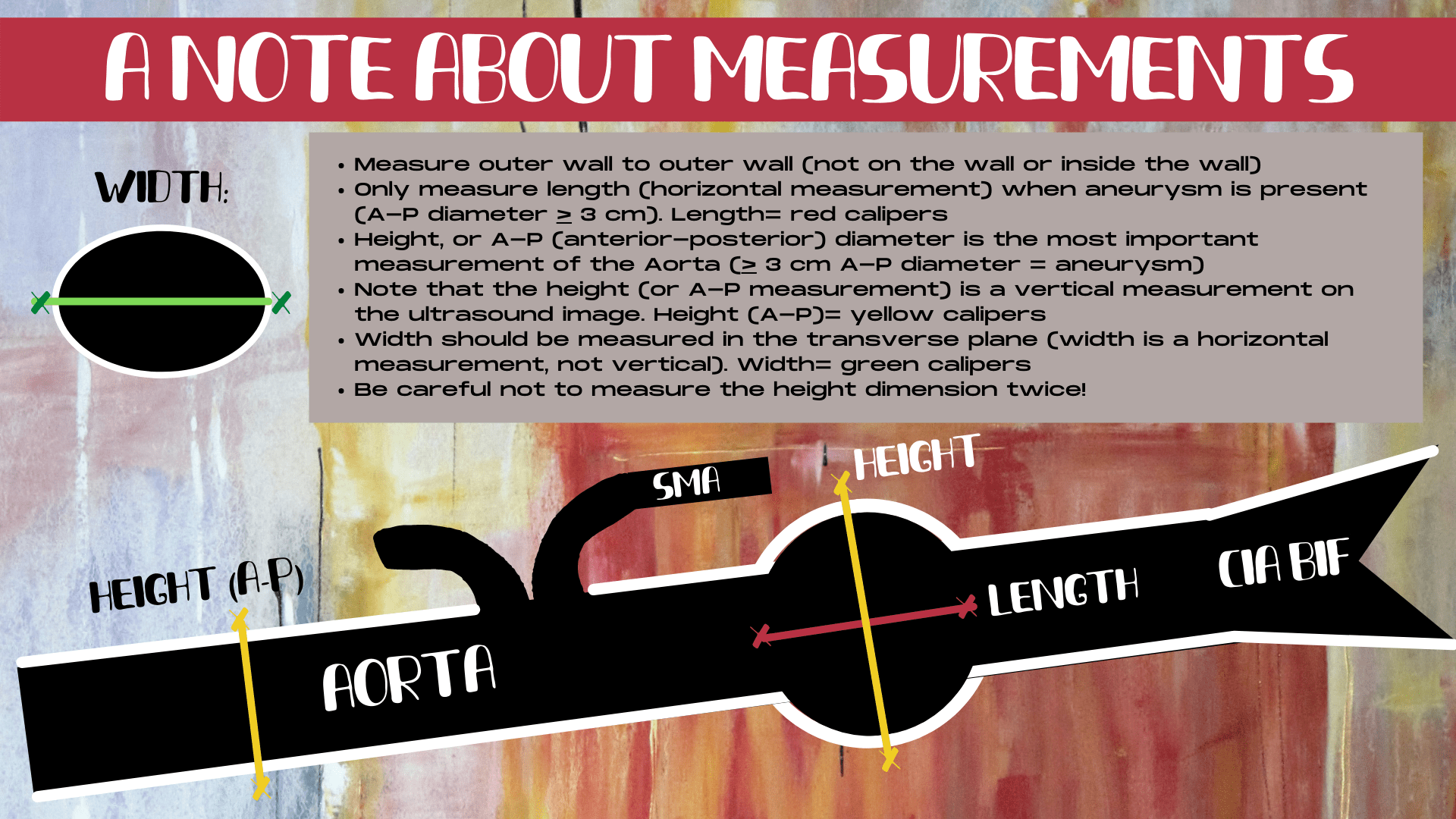
The height, or A-P dimension is the most important measurement in an aorta exam, delineating whether the aorta is dilated or not. The normal measurement for the proximal and mid aorta is 2 cm diameter or less, and the normal distal aorta measurement is 1.5 cm or less. The height dimension is most commonly measured in the sagittal plane as this is where the aorta can be elongated across the image to ensure that the aorta is not off-axis. Thus, it is the most accurate imaging plane for the aorta.
Since length (a horizontal measurement) is not routinely performed in an aorta exam, and the A-P dimension is measured in the sagittal plane, that leaves only one measurement dimension that still needs to be performed: the width. The width is traditionally performed in the transverse plane and it should always be a horizontal measurement on the image. Remember the three dimensions: horizontal, vertical, horizontal for every ultrasound exam. If the “width” is measured in a vertical direction on the ultrasound image, then this is not really a width, this is actually a second height dimension, which doesn’t provide value to the exam results.
So remember the mantra in your head when measuring anything in ultrasound: 2 horizontal measurements and 1 vertical measurement. Don’t produce two height measurements, and you’ll be well on your way to conquering the measurement calipers!
MEASURING THE COMMON ILLIAC ARTERIES
A note about measuring the common illiac arteries on ultrasound. In the sagittal plane, it’s crucial that the measurement calipers are placed 90 degrees perpendicular to the vessel walls for each illiac artery. Which means that the measurements will most commonly be at a different axis from one another. Sometimes both common illiac arteries can be visualized together and sometimes they can only be image one at a time. The crucial step is to elongate each artery as much as possible in the sagittal plane and measure just after the artery bifurcates, in a vertical plane, perpendicular to the lie of each common illiac branch.
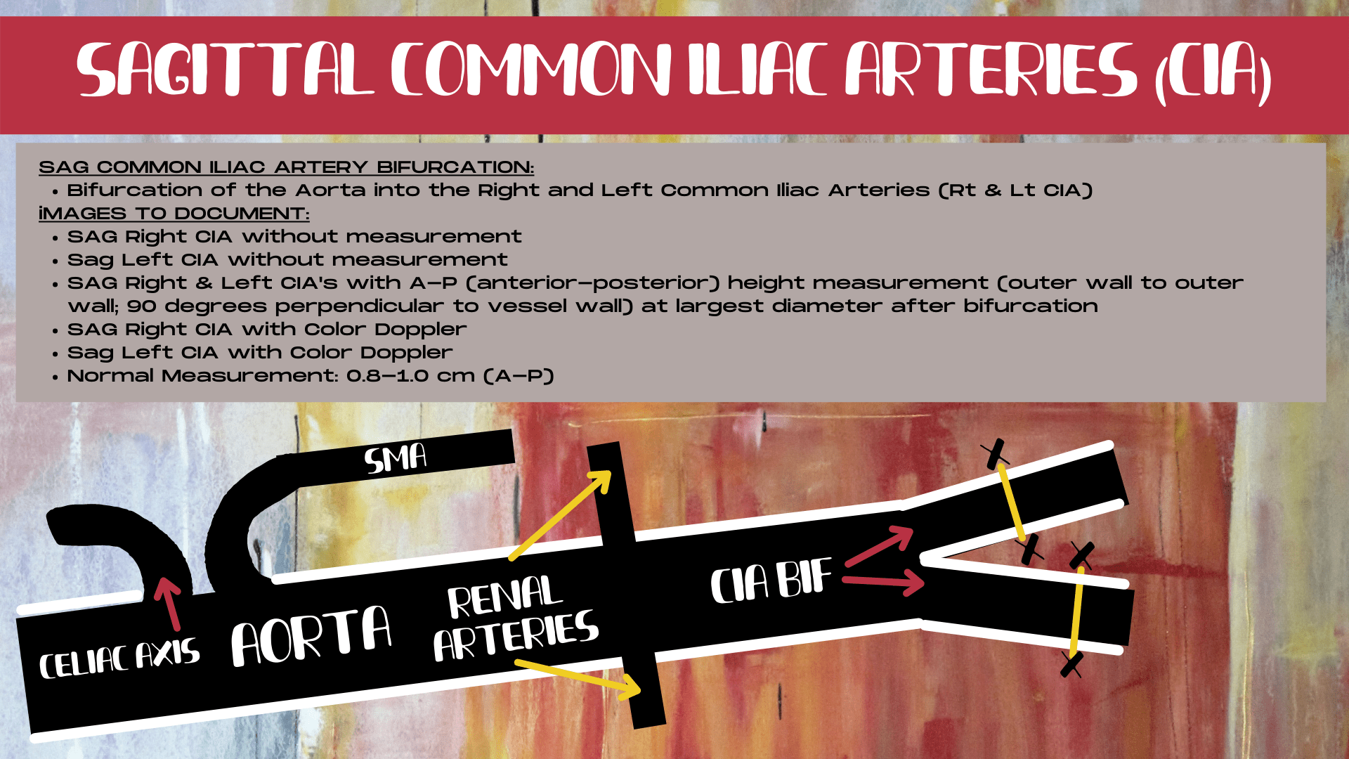
In the sagittal plane, the calipers should be placed 90 degrees perpendicular to the lie of each common illiac vessel. In the transverse plane, the longest lie of the oblong-shaped common illiac arteries should be measured (this is often a slightly oblique measurement, but still within a horizontal plane).
The common illiac arteries are often oblong in shape in the transverse plane. It’s important to measure the longest lie of the common illiac artery, as long as the longest lie is still in keeping with a relatively horizontal measurement. If the measurement becomes too vertical in nature, then you are measuring two height dimensions and not a true width. In this scenario, place the calipers closer to a horizontal plane even though it may not be the longest dimension (lie of the vessel in the transverse plane).
#4- STOP MIXING UP THE DIFFERENT SEGMENTS OF THE AORTA
Mixing up which segment of the aorta is which is one of the most common mistakes that aorta ultrasound newbies make. After all, the aorta is a long tube or a round ball, depending upon how you are looking at it, and it’s easy to mistake which portion of the aorta that you’re actually imaging. But mislabeling a segment of the aorta can lead to a potential mixup of the true location of any pathology that is found. Which can lead to confusion on any future follow-up ultrasounds or additional diagnostic tests. When performing any ultrasound, accuracy is everything!
WHICH SECTION OF THE AORTA ARE YOU IN?
Identifying the Proximal Aorta
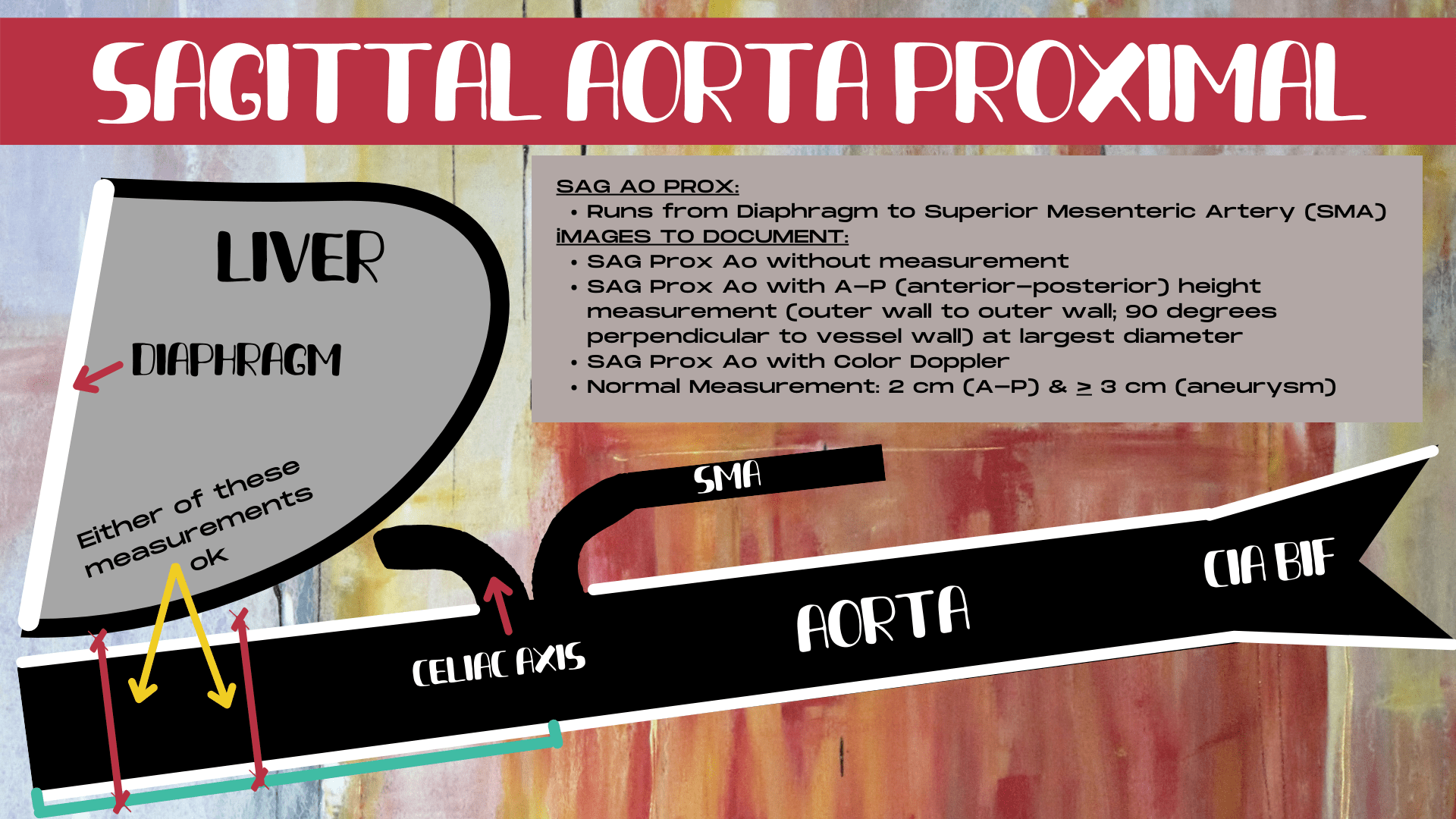
Which segment of that long tube or round ball of the aorta is which? Fortunately, the body has given us a precise roadmap to follow when identifying which segment of the aorta we are currently imaging. The proximal aorta runs from the diaphragm to the SMA. The divider between the proximal and the mid aorta is the SMA (superior mesenteric artery). This is the second branch off of the abdominal aorta, after the celiac axis, and it parallels the aorta, running above the sagittal aorta as a second long tube.
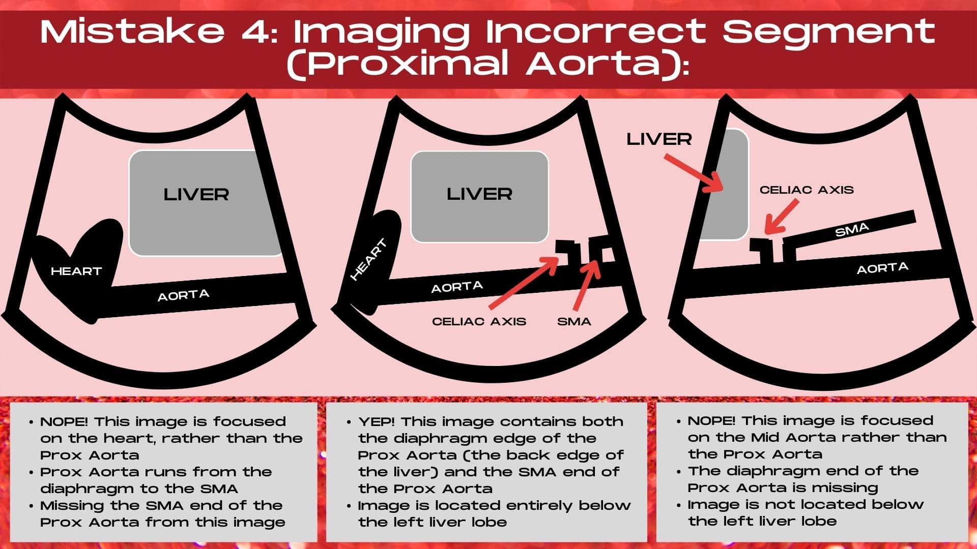
Identifying the Aorta Segment When Gas Gets in the Way
However, how can you tell which segment you are in if gas obscure the SMA region? The secret is to use the sagittal left lobe of the liver. The proximal aorta lies below the left lobe of the liver, and unless it is an elongated left liver lobe, once you are outside of being underneath the left lobe of the liver, you are generally going to be in the mid segment of the sagittal aorta.
The proximal aorta runs from the the diaphragm to the SMA and is largely located posterior to the left lobe of the liver on the ultrasound image.
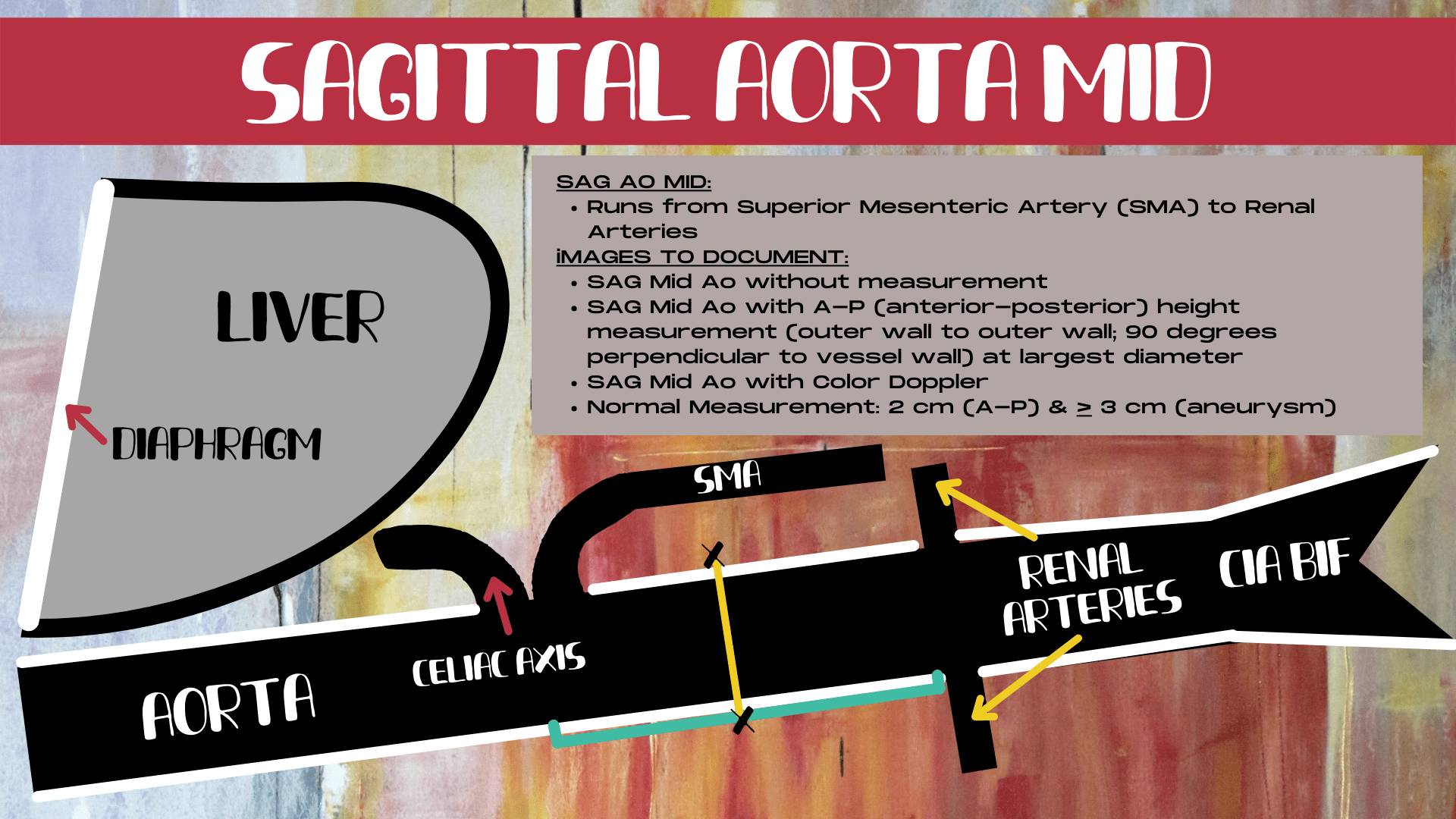
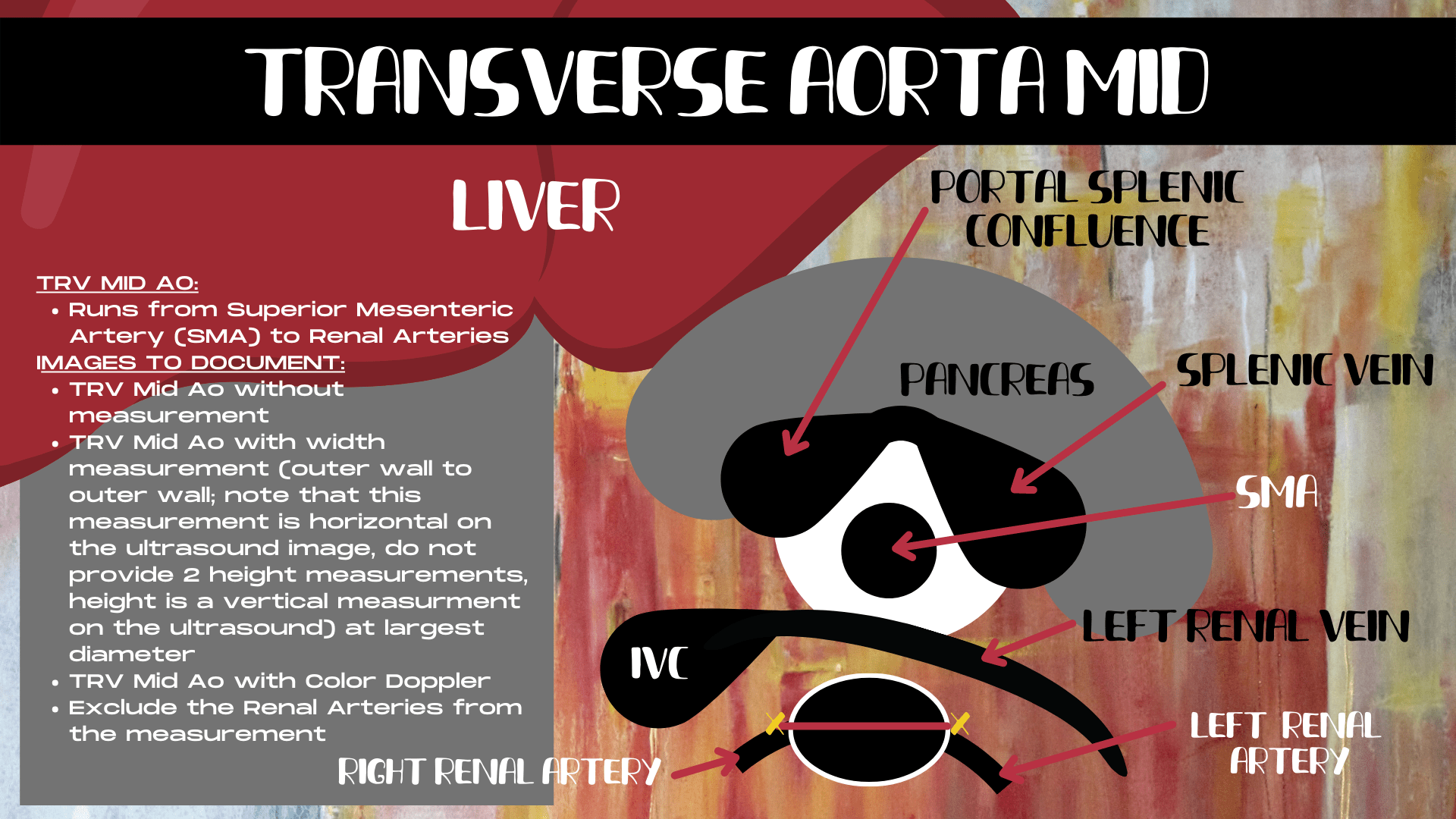
Identifying the Mid Aorta
The mid aorta runs from the SMA to the renal arteries. It’s easy to image the mid aorta too far distally. If the aorta is tapering and your transducer is down by the belly button, then you are down by the illiac bifurcation and need to more more proximally. It’s crucial to demonstrate the SMA junction in the image when imaging the sagittal mid aorta, unless this region is obscured by gas.
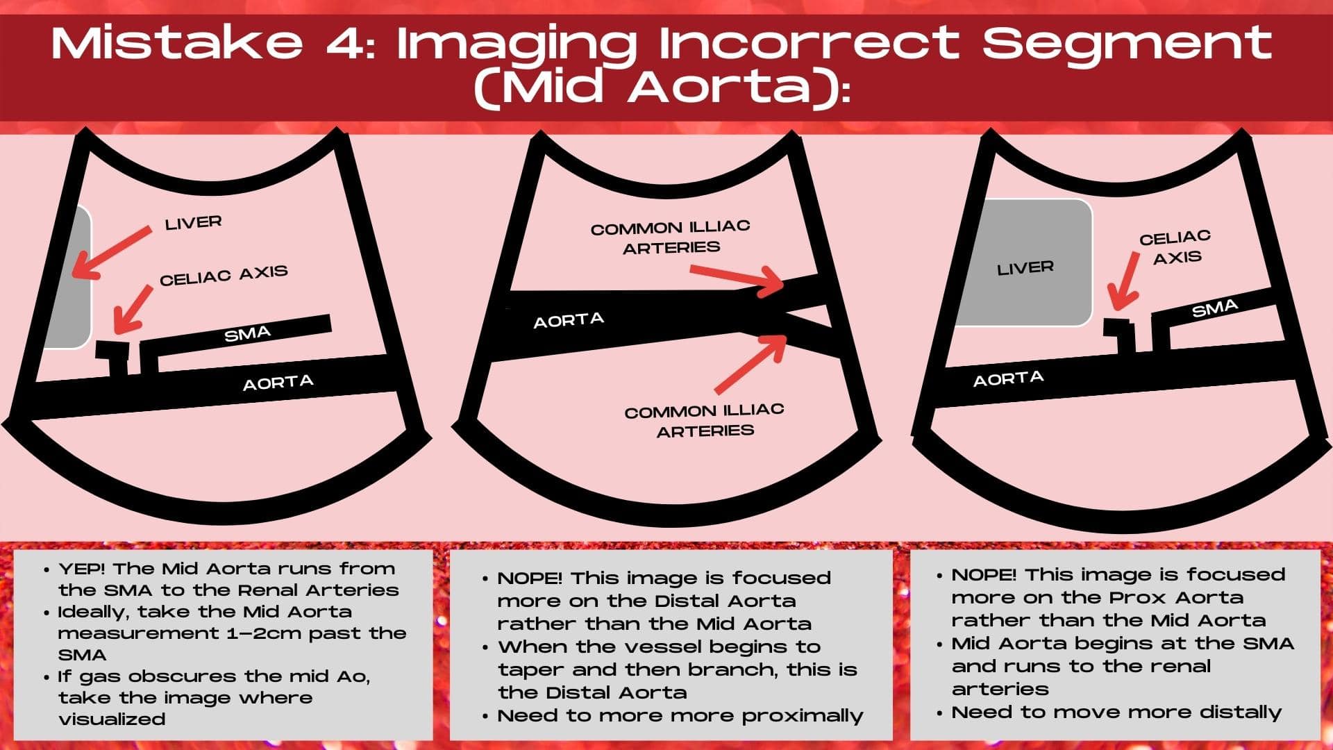
The mid aorta runs from the SMA to the renal arteries. It’s crucial to demonstrate the SMA/Aorta junction when imaging the sagittal mid aorta unless it’s obscured by gas.
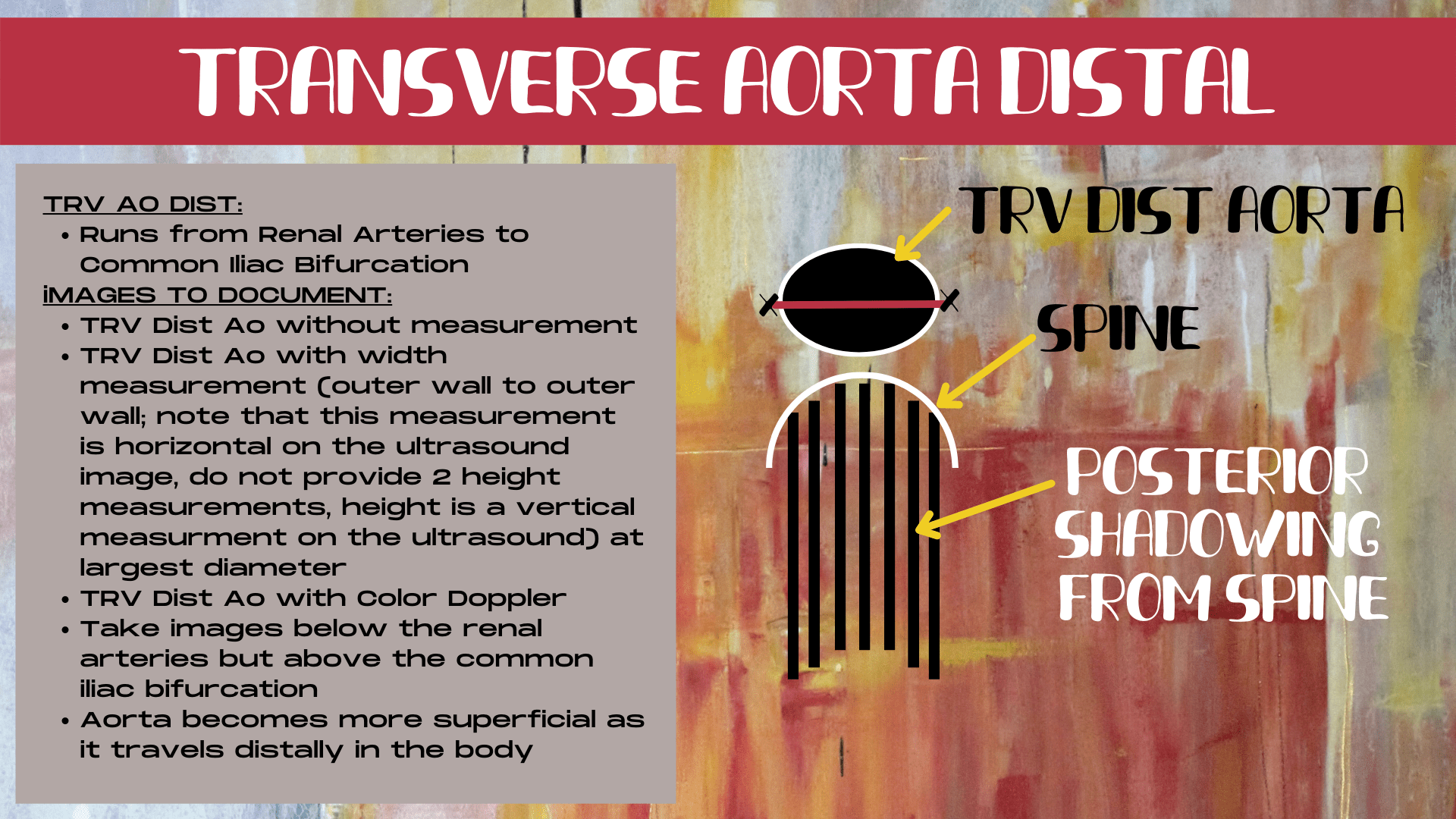
Identifying the Distal Aorta
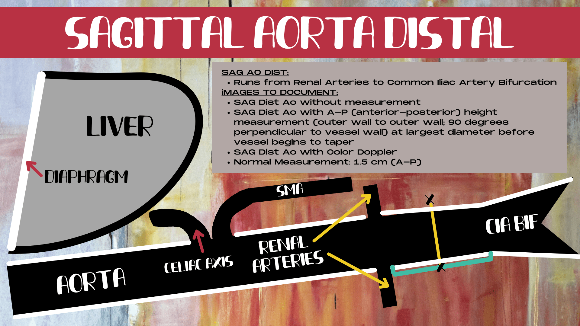
The distal aorta runs from the renal arteries to the common illiac bifurcation. The distal segment of the sagittal aorta is recognized by it’s depth (it moves more superficial in the body) and by it’s tapering end (it gets skinnier just before it bifurcates into the common illiac arteries). The most common mistake when imaging the distal aorta is not being distal enough. So if you cannot see the tapering end of the aorta, then you are too mid, and need to keep moving more distally. Also, look at where your transducer is. If you are not down by the belly button, then you are too high up in the aorta.
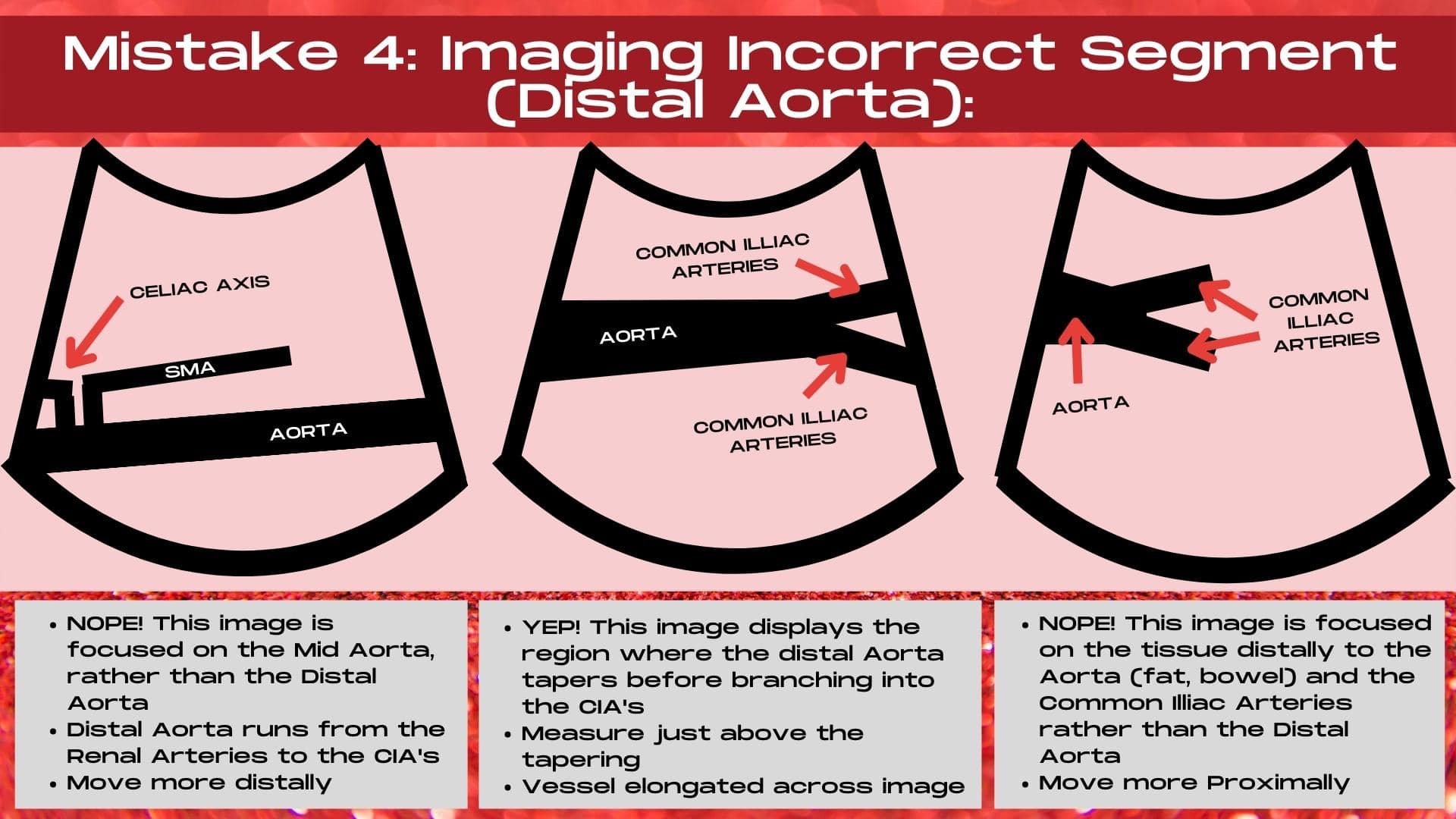
The distal aorta runs from the renal arteries to the common illiac artery bifurcation. It tapers in caliper in the sagittal plane before bifurcating.
Using Scanning Landmarks to Aid Identification
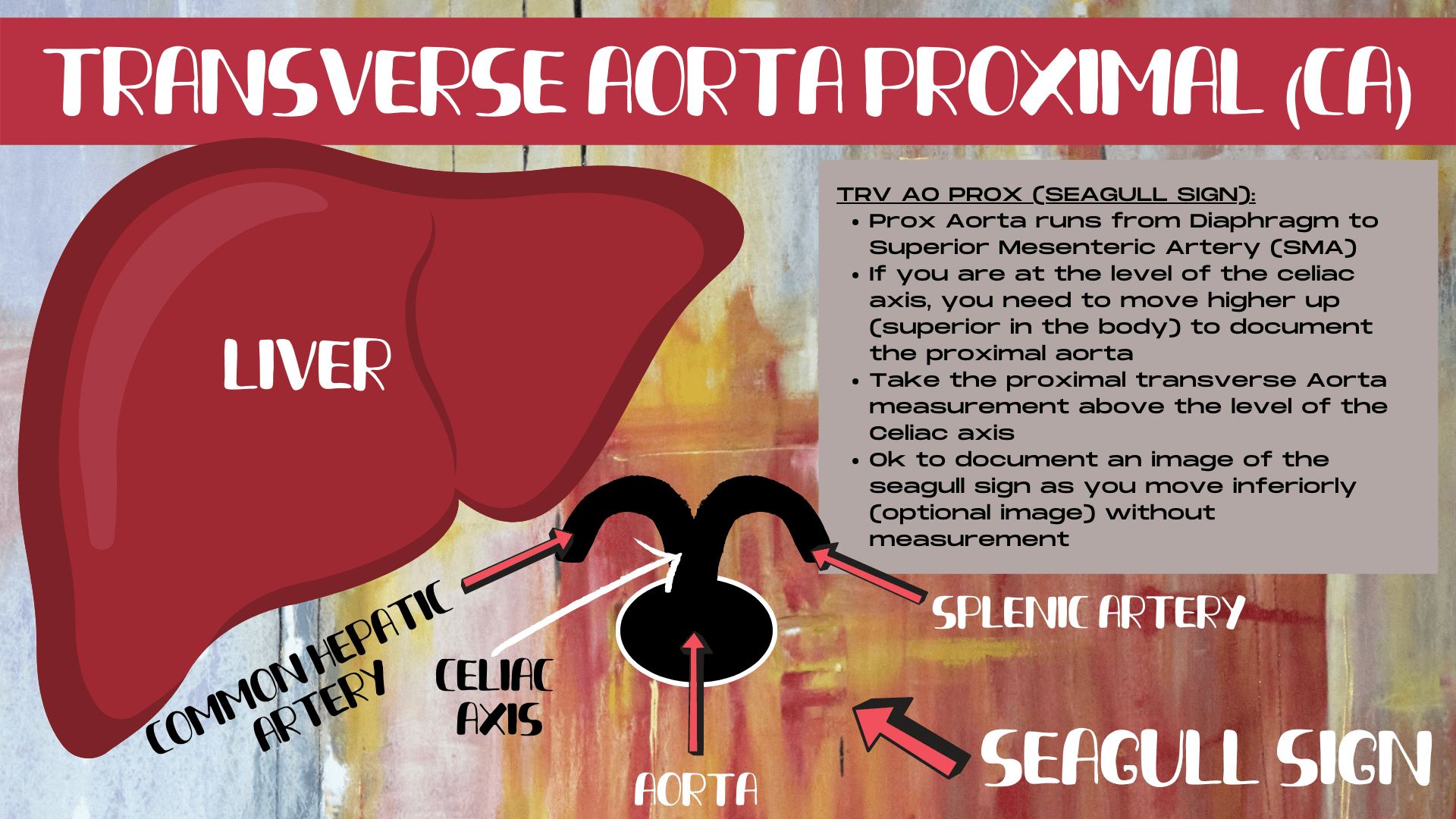
When imaging the transverse proximal aorta, find the seagull sign. This is the celiac axis and it’s branches. Move up higher, just past the seagull sign, and you are in the proximal transverse aorta. You should also be able to see the liver. If you cannot, then you are too far distal.
For the mid aorta, find the transverse pancreas and surrounding structures, we call this the raccoon sign on ultrasound. The “nose” of the raccoon is the SMA. The transverse mid aorta will be located below the SMA on the ultrasound image.
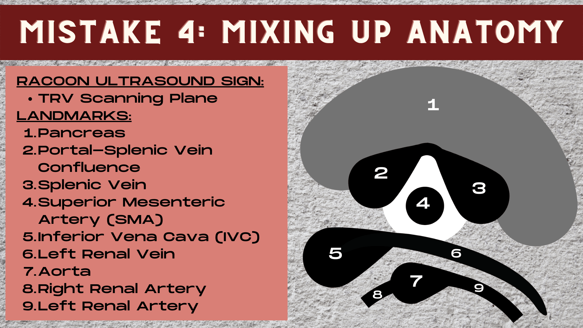
For the transverse distal aorta, move all the way down to the belly button, and watch the aorta bifurcate into the common illiac arteries. Then move up slightly, just above the illiac bifurcation, this is the distal transverse aorta.

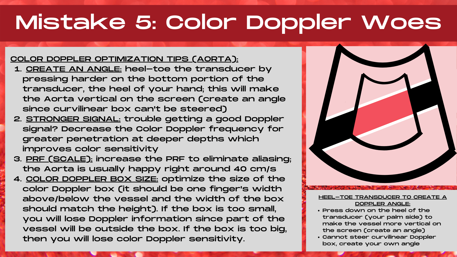
# 5- STOP USING COLOR DOPPLER INCORRECTLY
Struggling to obtain a Color Doppler signal in the Aorta? It’s likely your technique. Color Doppler optimization is an art form. One that is learned and finessed over time and many exams. However, if you learn how to apply these essential Color Doppler image optimization techniques from the start, you can make your Doppler signals strong and shave years of trial and error off your sonography journey.
HARNESSING THE POWER OF COLOR DOPPLER
COLOR DOPPLER SECRET 1- CREATE AN ANGLE
Why Angles Matter
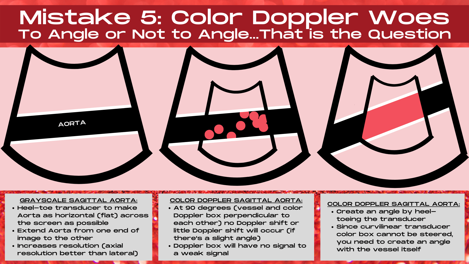
Doppler loves angles! The ideal Doppler angle is zero degrees, when the vessel lies completely vertical on the ultrasound image and the transducer and the vessel are parallel to one another. At 90 degrees, the ultrasound transducer and the vessel are perpendicular to one another, and no Doppler shift occurs. This results in no Color Doppler signal or a very weak Color Doppler signal on the ultrasound image. To get accurate Doppler shift information and obtain strong Color Doppler signals, angles between zero and 60 degrees are used. Angles from 61-89 degrees are inaccurate and cause flow velocities to be over or under estimated on ultrasound. So step one to creating the perfect Color Doppler image is to create an angle.
Create a Doppler angle by using the heel-toe transducer technique to cause the aorta to lie at an angle on the image rather than in a straight horizontal plane.
2 Methods of Creating an Angle
Now if you are using a linear transducer, an angle can be created in one of two ways, either the Color Doppler box can be steered left or right (so that it’s not straight on the image) or the transducer can be heel-toed in order to create a Doppler angle. This means pressing on either the heel portion of the transducer (near the palm of the hand) or the toe portion of the transducer (near the fingers) in order to make the vessel lie obliquely on the ultrasound image instead of horizontally. The best Color Doppler signal occurs when both techniques are applied: Doppler box steering and heel-toeing transducer techniques.
Doppler Angle & the Curvilinear Transducer
When using a curvilinear transducer, the Color Doppler box cannot be manually steered. Instead, the Color Doppler box is split into 3 sections.
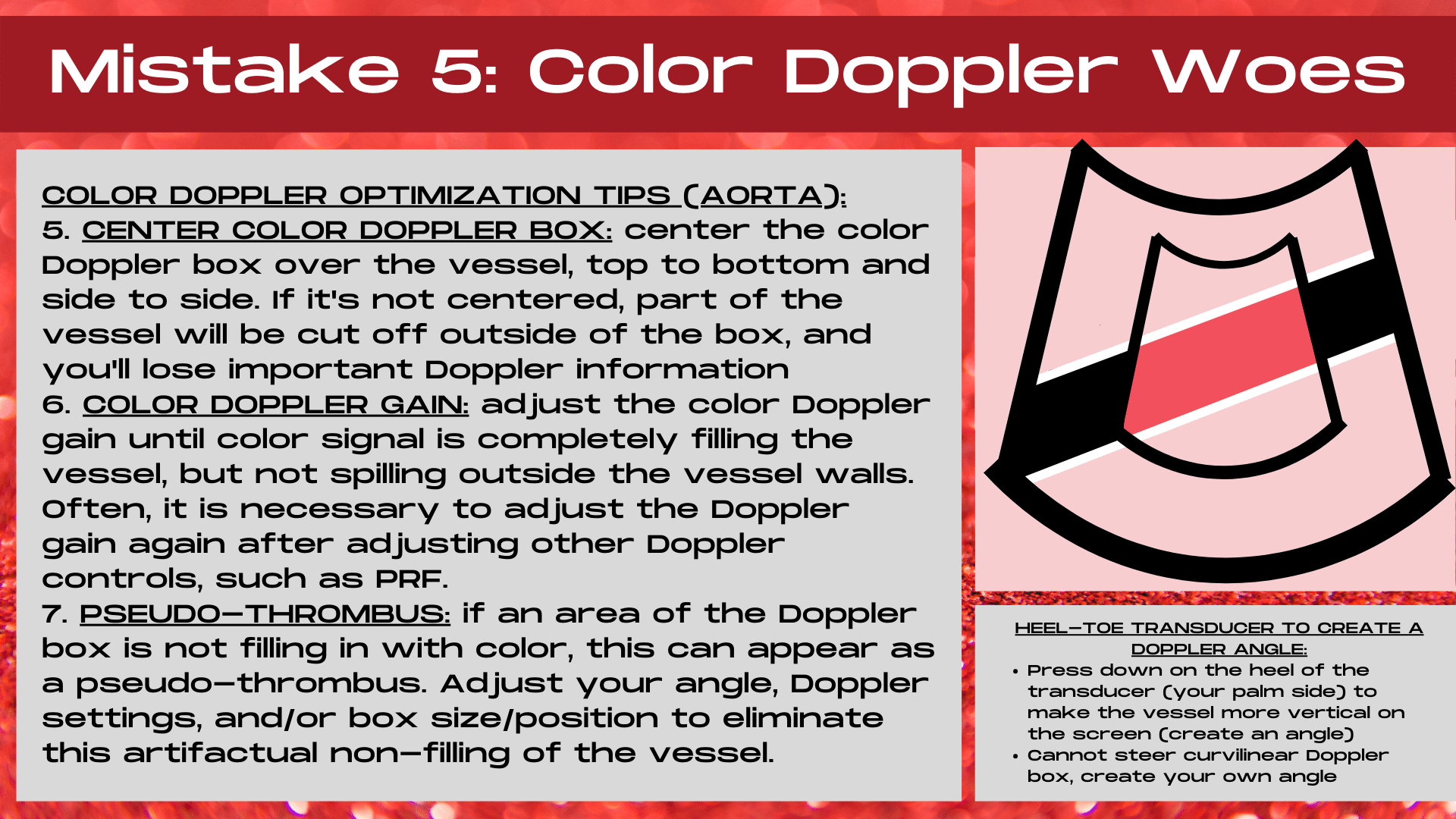
In the middle of the curvilinear Color Doppler box, the beam is angled straight down, and is unsteered. On the left side of the Color Doppler box, the ultrasound beam is steered to the right and on the right side of the Color Doppler box the ultrasound beam is steered to the left. In order to create a Doppler angle to obtain the best Doppler signal, the heel-toe technique must be applied to make the vessel lie obliquely on the image rather than horizontally.
COLOR DOPPLER SECRET 2- OPTIMIZE YOUR DOPPLER BOX SIZE & POSITION
Optimizing Doppler Box Size
It’s crucial to decrease the size of the Color Doppler box so that it’s not filling the entire screen or is larger than it needs to be. The larger the Color Doppler box size, the less the Doppler sensitivity will be. Decrease the size of the box so that it shows a segment of the aorta (about 1/4- 1/3 of the length of the aorta on the ultraosund image) and make the box height either slightly taller or equal to the box length.
It’s essential to optimize the size and position of the Color Doppler box so that important signal information is not located outside of the Doppler box and to provide the maximum amount of Doppler sensitivity.
Optimizing Doppler Box Position
Center the position of the Color Doppler box over the vessel so that it’s centered within the middle of the ultrasound image and also centered top to bottom, with equal amounts of normal tissue displayed both above and below the box. Ensure that there’s a rim of normal tissue both above and below the vessel, and that the top and bottom edges of the color box are not touching the anterior or posterior walls of the vessel. If the box is not centered, then important Doppler information that’s located outside the Doppler box can be lost.
COLOR DOPPLER SECRET 3- SETTING THE CORRECT COLOR DOPPLER GAIN LEVEL
Why the Doppler Gain Level is Key
Setting the correct Color Doppler gain level is a crucial step to ensuring that you are obtaining an accurate and a strong Doppler signal. If the gain is set to low, you might think that the vessel has little to no flow within it when it’s actually a normally behaving vessel. When the gain is set too high, artifact can mimic or obscure pathology within the Doppler box.
The optimal Color Doppler gain level provides both good Doppler sensitivity and eliminates unnecessary Doppler artifacts.
How to Set the Perfect Doppler Gain Level
To set the correct Color Doppler gain level, twist the Color Doppler gain knob until there’s extraneous color echoes within the Doppler box. It’s important to note that grayscale, Color Doppler, Power Doppler and Spectral Doppler all have their own gain setting, though Color and Power Doppler often use the same adjustment knob, which are essential to optimizing each control. Next, twist the Color Doppler gain knob down just until the extra speckles disappear. This is the optimal Color Doppler gain level, providing both good Doppler sensitivity and eliminating unnecessary artifacts.
COLOR DOPPLER SECRET 4- IT’S ALL ABOUT THE SCALE
Nyquist Limit
Doppler has a limit, past this limit the ultrasound machine can no longer measure the velocity of the flow because it is too high. This is known as the Nyquist limit, and it’s the maximum limit of the Doppler shif that can be measured and displayed by the ultrasound machine. Above the Nyquist limit, aliasing occurs. If the range of displayed velocities is set too low, then aliasing occurs within the Doppler signal. The Nyquist limit is 1/2 of the PRF.
Aliasing
Aliasing is flow that changes speed and direction either due to vessel dynamics or improper machine settings. Aliasing appears as multiple colors displayed within a structure or vessel on Color Doppler. Artifactual velocites occur when the velocity of the flow has exceeded the Nyquist limit. Aliasing can also represent true velocites such as within areas of vessel narrowing, curvature or branching.
PRF/Scale Ultrasound Control
The ultrasound PRF, or scale control can be adjusted to correct for artifactual aliasing. Ultrasound pulses are transmitted at a certain frequency. The number of pulses of sound that occur in one second is known as the PRF, or pulse repetition frequency. The ultrasound PRF or scale control increases or decreases the range of velocities that the ultrasound machine can detect. It changes the range of velocities displayed on the Color Doppler map.
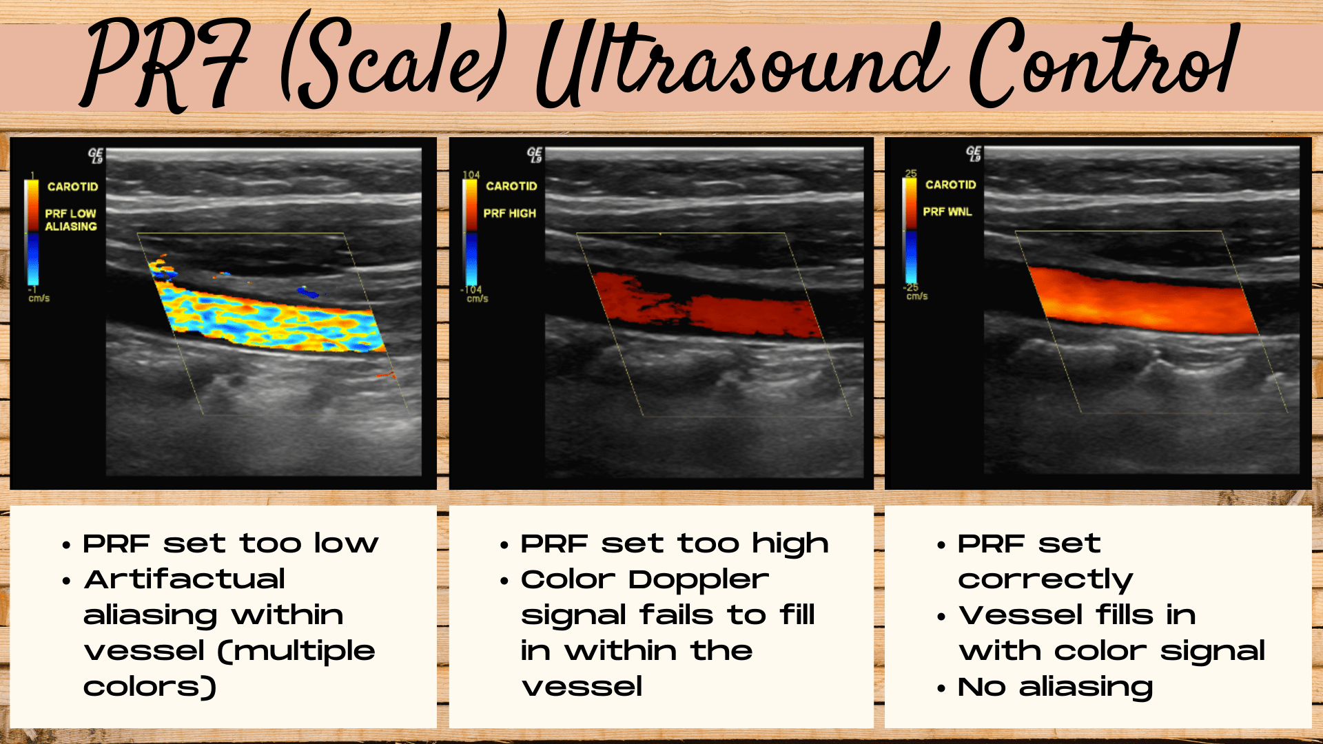
If the PRF is set too low when using Color Doppler, then aliasing (multiple colors) will occur within the vessel. If the PRF is set too high, the vessel will fail to fill all the way in with a Color Doppler signal. A correct PRF or scale setting will allow the vessel to fill with color signal and eliminate artifactual aliasing.
Setting the correct PRF level is a balancing act between eliminating aliasing in the vessel and filling the vessel with Color Doppler signal.
BONUS COLOR DOPPLER SECRET- BEWARE OF PSEUDO-THROMBUS IN YOUR IMAGE
What is Ultrasound Pseudo-Thrombus?
Sometimes, an area of the Color Doppler box within the vessel fails to fill in with a Color Doppler signal. In the absence of thrombus or other pathology, this can be an artifact known as a pseudo-thrombus (an area of perceived thrombus that’s not real pathology). Most commonly it’s due to improper angle, when a segment of the vessel is either perpendicular to the transducer (where no Doppler shift will occur) or due to an unusally large Doppler box, which provides low Doppler sensitivity, causing portions of the box to fail to fill with Doppler signal. It may also be due to a PRF setting that’s too high, resulting in poor color signal (filling) within the vessel.
“Pseudo-thrombus” can occur in a vessel due to lack of a Doppler angle, a PRF setting that’s too high or due to a Doppler box that’s too large or improperly positioned.
How to Eliminate Pseudo-Thrombus
To eliminate pseudo-thrombus, first adjust the angle by either steering the Color Doppler box (when using a linear transducer) and/or by heel-toeing the transducer to create an angle with the vessel itself. Optimizing the Color Doppler gain, the Doppler box size and postion and PRF settings can also help eliminate pseudo-thrombus.
Whew! We’ve covered a lot today. You’ve discovered the keys to always recognizing the aorta versus the IVC. You’ve learned the ins and outs of ensuring that your Aorta images are on-axis, no matter which imaging plane you are in. We covered the right way (and the wrong way) to measure the Aorta in 3 different dimensions. Next up was making sure that you are within the correct segment of the Aorta by using surrounding structures as a roadmap. And we wrapped things up by diving into the secrets of Color Doppler image optimization for an aorta ultrasound. Next time you encounter an Aorta Ultrasound, you can dive in with confidence, knowing that you have the tools to make your Aorta images dazzle!
READY FOR MORE DOPPLER TIPS AND TRICKS? READ THIS NEXT- DOPPLER ULTRASOUND: 9 SECRETS TO THE PERFECT IMAGE.